📻 CQ PE1NAO (Netherlands · JO32) on 7.075 MHz FT8 at 12:51 UTC
Full Level: Transmitters and receivers
Full Level: Transmitters and receivers
Part of the official RSGB Full Level question bank, filtered to the Transmitters and receivers syllabus section.
156 questions in this section
Some questions include a reference diagram or circuit image
Full Level - Syllabus V1.6b
Before you start, you may want to open the official RSGB reference data sheet
(band plans, frequency tables, conversions) — it's allowed for use during the real exam too.
🔀 Practice Mode — random question, not scored. Click an option to reveal the answer.
2025-Full381
A wideband FM transmission is one where the
2025-Full7637
In frequency modulation if the audio input is increased in amplitude then the
2025-Full7742
An FM transmission has only two sidebands, one above and one below the carrier. That must mean that the
2025-Full7772
The Modulation Index of a frequency modulated transmission is given by
2025-Full7773
As the Modulation Index of an FM transmission increases it is <strong>ALWAYS</strong> the case that the
2025-Full7774
The spectrum of an FM signal is being displayed on a spectrum analyser which is showing the individual sidebands generated by a single audio tone of variable frequency and amplitude. An increasing number of sidebands must mean that the
2025-Full3408
A transmitter performs all the modulation functions at a fixed frequency of 8.0MHz and then mixes the modulated signal up to 145MHz. What frequency should the filter following the balanced mixer take particular care to REJECT.
2025-Full3598
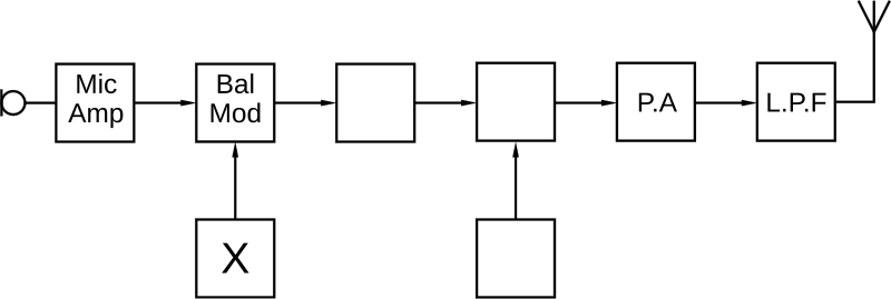
The box marked 'X' in the SSB transmitter shown is the
2025-Full3600
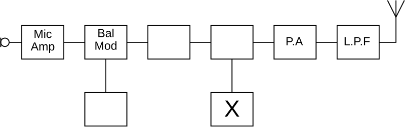
The box marked X in the FM transmitter shown is the
2025-Full3602
The box marked 'X' in the SSB transmitter block diagram is the
2025-Full4078
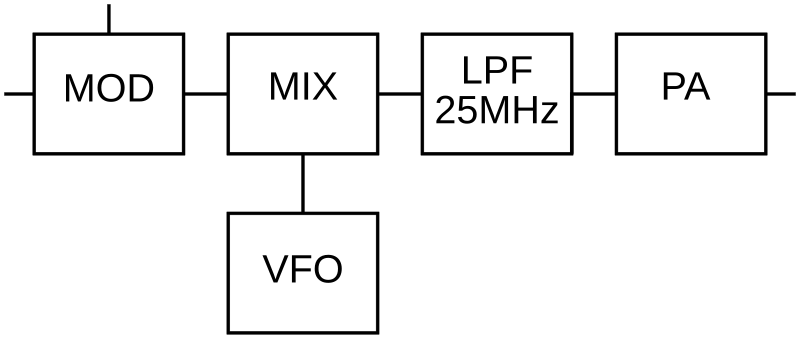
The diagram shows part of a transmitter for the 21MHz band. The modulator is operating at 8MHz. A good choice of frequency for the VFO is
2025-Full682
The purpose of a buffer amplifier stage is often to
2025-Full8029
The oscillator in an HF transmitter is based on an LC tuned circuit and is specified as having a maximum drift of 0.1%. An important effect of this is that a CW signal in the 10MHz amateur band
2025-Full3410
A transmitter being used on 432.2MHz SSB is known to have a very small frequency error but a high temperature dependent drift of approximately 2ppm per degree C. A temperature rise of 10 degrees C is not unusual. The most significant effect of this is likely to be
2025-Full3987
Which situation is likely to result in drift in the first 5 to 10 minutes after starting operation?
2025-Full7897
What is the most likely effect of a transmitter on 145.000MHz suffering from severe drift of the order of 200ppm?
2025-Full3606
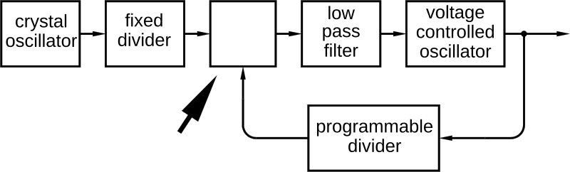
In the block diagram of a frequency synthesiser the arrowed box contains
2025-Full7743
What function is performed in the box marked X?
2025-Full3349
When a sinusoidal output is produced from a direct digital synthesiser (DDS), the number of bits the synthesiser can generate will affect the
2025-Full3406
The size of the frequency steps in a phase locked loop frequency synthesiser is set by the
2025-Full354
If a sine wave is produced by direct digital synthesis, the purity of the output is determined mainly by the
2025-Full3791
When a sine wave is produced from a direct digital synthesiser, the number of bits the synthesiser can generate will affect the
2025-Full365
Why do frequency multiplier stages usually operate in Class C?
2025-Full368
A single-channel transmitter intended for operation on 70.26MHz uses a crystal oscillator on 5855kHz. The final frequency is most likely to be produced by
2025-Full374
The function of the multiplier stage in a transmitter is to
2025-Full688
It is proposed to generate a microwave signal by feeding the output of a UHF transmitter to a frequency multiplier circuit. This arrangement is suitable for use with
2025-Full738
A modulated UHF signal is available to feed a 10GHz microwave transmitter. The transmitted frequency is 10.38GHz. A suitable multiplier frequency for the UHF source is
2025-Full384
Which of the following modulation types is often generated by varying the voltage applied to a varicap in an RF oscillator?
2025-Full391
Increasing the deviation level of a frequency modulated transmitter
2025-Full393
A single sideband transmitter is operating on lower sideband on 1.960MHz and is modulated with a pure 3000Hz tone. The RF output frequency will be
2025-Full683
In an amateur radio transceiver, the depth of modulation for radio telephone transmissions can be varied by use of the
2025-Full686
A 1MHz carrier is frequency modulated by a 1kHz audio signal amplitude 100mV and causing a peak deviation of 2.5kHz. The occupied bandwidth of the transmission is approximately
2025-Full716
An FM broadcast transmitter uses a peak deviation of 75kHz and a maximum audio frequency of 15kHz. The bandwidth of the transmission is approximately
2025-Full7745
The circuit shown is likely to be found
2025-Full7746
A transmitter is set to 7.150MHz LSB. The balanced modulator has a 6.000MHz carrier and its output will subsequently be mixed up to the transmit frequency by a synthesiser on 13.150MHz. The sideband filter should be set to pass
2025-Full7775
A superhet receiver is tuned to an upper sideband signal on 144.500MHz. The local oscillator is running at 140.500MHz. The sideband filter to admit the signal should be set to
2025-Full7778
A superhet receiver is tuned to a lower sideband signal on 144.500 MHz. The local oscillator is running at 148.500 MHz. The sideband filter to admit the signal should be set to
2025-Full7779
In the circuit shown the crystals are set to 9.0 MHz, the capacitors to 39pF and the overall Q factor is 3330. What is the most likely function of the circuit?
2025-Full7780
A crystal filter 2.7kHz wide is used to select the wanted sideband in the IF of a superhet receiver. Rather than set up another filter for the other sideband an alternative option is to offset the local oscillator by
2025-Full398
You are intending to add an SSB transmit amplifier to your Station. The amplifier should be
2025-Full399
An RF power amplifier operates class C. It is suitable for
2025-Full717
A good SSB transmitter is feeding a power amplifier that is rather non-linear but does have a good low pass filter on its output. The most significant effect of the non-linearity will be
2025-Full7785
A non-linear amplifier fed with two sinusoidal input signals will produce
2025-Full7787
An SSB RF amplifier is being driven by two RF signals at 14.101 MHz and 14.102 MHz when it is noticed that there is also an output on 14.103 MHz. What action is most likely to clean up the signal?
2025-Full7788
The drawing shows the spectrum of the input and output of an external RF power amplifier being fed from an SSB transmitter. The most likely explanation for the change in the spectrum is that
2025-Full402
A pi-network in the output stage of a transceiver
2025-Full403
In a transmitter PA stage a pi-network is used for impedance matching. It also can act as a
2025-Full405
The output circuits of an RF power amplifier normally fulfil two functions, filtering and
2025-Full408
Which mode of transmission will result in the greatest average power requirement from the final amplifier? Assume the PEP is the same in all cases.
2025-Full409
The effect on the RF power amplifier of switching on speech processing in an SSB transmitter will be
2025-Full410
A transmitter is normally used on SSB and runs comfortably warm even when peaking at 100W output. It is decided to use the same transmitter on RTTY (radio teletype) and the input level is set so the RF output peaks at the same level as previously used on voice. It is likely that the transmitter will run
2025-Full411
A class AB transmitter has been in use for some time and the speech processor is then switched on and set to maximum compression. The peak transmit power is seen to be unaffected. It is LIKELY that the transmitter will run
2025-Full412
Using a speech processor in an SSB transmitter will
2025-Full3280
A transceiver is fitted with an automatic level control (ALC). This will
2025-Full413
The purpose of Automatic Level Control (ALC) in a transmitter is to
2025-Full415
An external RF power amplifier (PA) has 3 leads marked '240V AC', 'RF in' and 'ALC'. The ALC lead
2025-Full697
A transceiver is fitted with an automatic level control (ALC). This will
2025-Full3411
Over modulation of an RF carrier is likely to result in
2025-Full4081
When the spectrum of an HF AM transmitter is observed over a narrow range, it is noticed that as the modulation depth is changed there is a point beyond which several harmonics of the audio signal appear. At that point the depth of modulation will be
2025-Full474
Over modulation of an SSB transmitter results in excessive RF bandwidth because the greater amplitude of the AF signal causes
2025-Full475
Even though your microphone amplifier has good audio frequency bandwidth filtering you find that your transmissions occupy excessive RF bandwidth. A likely cause is
2025-Full476
Over modulation may be caused by excessive
2025-Full3990
A cause of intermodulation products in a separate RF power amplifier (PA) is
2025-Full485
Overdriving an external power amplifier with a transmitter is likely to
2025-Full486
An operator should not overdrive an external power amplifier with a transmitter in order to avoid
2025-Full489
You should not overdrive an external power amplifier so as to avoid
2025-Full7789
The drawing shows the spectrum of the input and output of an external RF power amplifier. It is most likely that the
2025-Full7790
An amateur is receiving complaints that his transmissions are causing interference to other stations immediately above and below his transmitted frequency. The amateur should check that
2025-Full430
Harmonics in a transmitter would NOT be reduced by using
2025-Full432
Which of the following is most likely to cause harmonics?
2025-Full465
The response of a transmitter's low pass filter should fall sharply above the cut off frequency to attenuate the transmission of
2025-Full466
A low-pass filter fitted at the output of a transmitter will
2025-Full467
A transmitter for the 160 metre band is found to radiate on other amateur bands. What action could be taken to prevent this?
2025-Full4080
An FET HF RF power amplifier occasionally suffers from parasitic oscillation at a frequency much higher than the designed operating frequency. Which of the four options is most likely to be successful?
2025-Full469
Stray coupling in a Power Amplifier may be the cause of
2025-Full470
Unwanted parasitic oscillations may occur as a result of
2025-Full472
The lead to the base of the power amplifier transistor in an RF PA is connected via a low value resistor with a few turns of wire, wound round the resistor and in parallel with it. The purpose of this circuit is to
2025-Full473
Parasitic oscillations in a transistor amplifier may often be cured by
2025-Full3412
A phase locked loop synthesiser in a transmitter has an output to indicate that the control loop is phase locked. If this indication is absent it is necessary to
2025-Full3617
If a phase lock loop frequency synthesiser indicates an 'out of lock' condition the signals into the phase comparator
2025-Full4082
It is noticed that a home made frequency synthesiser can briefly produce an output signal of unstable frequency when quickly tuning from from one end of an amateur band to the other. The probable reason is that
2025-Full479
With which part of the circuit of a transceiver is the term 'out of lock' associated?
2025-Full480
The term 'Out of lock' is a type of malfunction associated with a
2025-Full482
If a frequency synthesiser is 'out of lock', its output should be
2025-Full495
In a receiver, the difference between the maximum signal that can be received without overload and the minimum signal that can be discerned is the
2025-Full496
The dynamic range of a receiver is expressed in
2025-Full497
A receiver can just audibly detect signals of 0.4µV (Negative (-)145dBW) at its input. The receiver overloads at an input of 10mV (Negative (-)57dBW) causing intermodulation products that can be heard as false signals. The dynamic range of the receiver is
2025-Full508
A strong signal into the front end of a radio receiver exceeds its dynamic range. An effect of this will be
2025-Full509
Spurious signals in a receiver could be caused by
2025-Full7791
The dynamic range of a radio receiver is usually expressed in which units?
2025-Full3621
The IF stage has been omitted from the block diagram of a superhet receiver. At what point should it be inserted?
2025-Full3623
The block diagram shows a superhet receiver. G represents an audio amplifier. What is block F?
2025-Full3816
What is the main purpose of having two intermediate frequencies in a double superhet receiver?
2025-Full3944
In a double conversion super-heterodyne receiver, to which part of the circuit would you normally connect the BFO?
2025-Full505
A double superhet receiver designed to receive and demodulate SSB is likely to contain
2025-Full3425
To what frequency should the local oscillator 'X' be set to ensure successful operation?
2025-Full3628
A superhet receiver is tuned to 1.3555 MHz. The LO could also have been operating on
2025-Full3686
A superhet receiver is set to receive 1.820 MHz and the LO is running at a frequency of 1.355 MHz. An alternative frequency for the LO is
2025-Full515
In a superhet receiver the mixer
2025-Full516
The mixer combines the LO at 2MHz with the RF signal to produce an IF at 470kHz. The other principal output signal from the mixer will be on a frequency of
2025-Full517
A medium wave radio receiver to tune from 600kHz to 1600kHz and has an IF of 460kHz. The best choice of local oscillator frequency range will be
2025-Full512
A receiver is being designed to receive a medium wave broadcast on 1.000MHz. The local oscillator is set to 1.465MHz. For the same IF, what other frequency could the local oscillator be set to?
2025-Full513
An HF radio receiver is tuned to 1.85MHz and the IF is at 460kHz. The local oscillator will be at
2025-Full518
In a 14MHz superheterodyne receiver that has a 9MHz Intermediate Frequency the image frequency will be on
2025-Full520
A receiver tuned to the 7MHz amateur band, with a single IF of 455kHz, might suffer from second channel interference from stations around the frequency
2025-Full524
In a superheterodyne receiver a low Intermediate Frequency is an advantage because
2025-Full531
It is desired to achieve both a good image rejection and good adjacent channel selectivity in a radio receiver. This can be done by using a
2025-Full3629
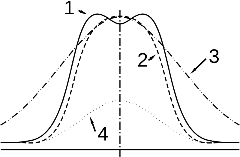
Which curve in the drawing shows a critically-coupled response?
2025-Full532
An Intermediate Frequency transformer is said to be 'critically coupled' when it uses
2025-Full534
The selectivity of a superheterodyne receiver is determined mainly by the
2025-Full535
Reducing the gain of an IF amplifier stage by changing the bias has the side effect of causing distortion. This distortion is removed by
2025-Full536
The AGC voltage from the detector stage of a receiver varies the gain of the IF stages by
2025-Full537
In a typical IF amplifier the coupling between the stages is normally by means of
2025-Full7641
Phase noise is likely to be significant in the output from
2025-Full7643
What is the mechanism by which poor phase noise on an oscillator degrades transmitter performance?
2025-Full7693
The level of phase noise is normally given in units of
2025-Full7694
Phase noise is a feature often associated with
2025-Full7797
An important effect of severe phase noise in a transmitter is
2025-Full8031
Why does fitting an RF preamplifier to an HF receiver not necessarily result in being able to receive weaker signals?
2025-Full3626
A old UHF receiver has a quoted sensitivity on 0.32uV (Negative (-)117dBm) for 12 dB S/N. Overload is at 10mV (Negative (-)27dBm). To improve its sensitivity a pre-amplifier is inserted between the feeder and the receiver with a gain of 12dB and 8dB less internal noise. The dynamic range is
2025-Full3802
It is proposed to fit a pre-amplifier to an existing receiver. Which combination is likely to show the greatest overall improvement?
2025-Full7697
Locating an RF preamplifier at the antenna end of the feeder rather than the receiver end will typically improve the signal to noise ratio of weak signals by
2025-Full7698
It is often found that adding a preamplifier to an HF receiver has little effect on the signal to noise ratio of weak signals. Why might this be so?
2025-Full7900
A 70cm receiver has a long feeder to an antenna at the far end of the garden. To improve reception of weak signals a low-noise pre-amplifier is fitted alongside the receiver. The improvement in signal to noise ratio is noticeable but not impressive, certainly only a fraction of the expected improvement given the gain of the pre-amp. To try to further improve matters it is worth
2025-Full3633
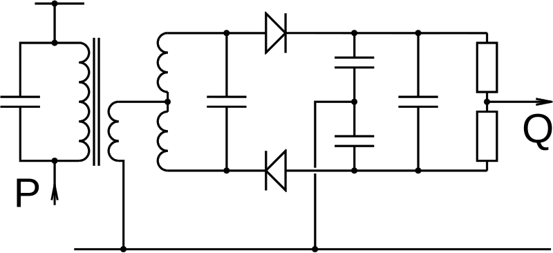
What signals should be at the points 'P' and 'Q' in the drawing?
2025-Full540
Which of the following modes of modulation can a product detector resolve?
2025-Full543
Which mode of signals is demodulated with a ratio detector?
2025-Full7699
One advantage of a fast attack in the response of the AGC circuits is that
2025-Full7700
The AGC signal is derived from the
2025-Full7750
What does the term 'attack' refer to in the operation of the AGC in a receiver?
2025-Full7751
What does the term 'decay' refer to in the operation of the AGC of a receiver?
2025-Full7799
What settings might be provided to operate the AGC in a receiver?
2025-Full7901
In a superheterodyne receiver the AGC control voltage is usually the
2025-Full6022
Modulating a carrier with digital data can
2025-Full6023
The solid arrow in the phasor diagram represents the carrier and the dashed arrows represent sidebands. What type of modulation is being portrayed?
2025-Full6024
The solid arrow in the phasor diagram represents the carrier and the dashed arrows represent sidebands. What type of modulation is being portrayed?
2025-Full6027
The diagram shows a phasor diagram representing the positions occupied by a particular type of data modulation. In order to recover the data an SDR demodulator needs to
2025-Full7902
If the amplitude and phase of an incoming RF signal can be captured with reasonable accuracy
2025-Full8034
An oscillator is designed to have two outputs at the same frequency but with a phase difference of 90°. It is most likely that the oscillator is an essential part of
2025-Full8035
The drawing shows part of the block diagram of a radio device. It is likely to be an essential part of an
2025-Full6028
To capture both the amplitude and phase of a received signal in an SDR receiver it is necessary to
2025-Full6029
In order to use digital processing to tune to and demodulate a radio signal it is necessary to employ a mixing process where the incoming RF signals
2025-Full6030
Why is it necessary to utilise both an 'I' and a 'Q' signal when they are both derived from the same incoming signal?
2025-Full7800
An alternative to using local oscillators and mixers to extract the I and Q streams from an incoming radio signal is to
2025-Full554
In a modern transceiver which of the following would be shared between transmit and receive circuits?
2025-Full556
In a modern transceiver which of the following would NOT be shared between transmit and receive circuits?
2025-Full557
The RIT control on a radio transceiver
2025-Full558
The purpose of the RIT control on a transceiver is to
2025-Full559
When operating HF SSB in a net of several stations, it is noted that the stations are all transmitting on slightly different frequencies. A good way of improving reception is to adjust the
2025-Full700
A transceiver will often share circuits between transmitter and receiver. Typically this would include the
2025-Full3635
Which amateur band is the receive converter shown intended to cover?
2025-Full3636
The receive converter shown is designed to receive which amateur band?
2025-Full3637
Which amateur band will the receive converter cover?
2025-Full552
An HF operator who wishes to operate on UHF can do so by adding a
2025-Full553
In order to operate cross-band with VHF receive and HF transmit, an HF operator could use
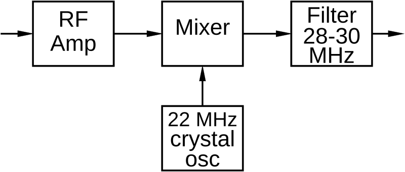
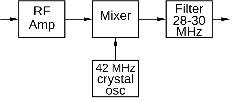
2025-Full7905
It is desired to operate on 2m SSB using the station 10m, 28-30MHz, transceiver. This can be done with a suitable mixer and crystal oscillator. What is the best choice of crystal frequency?