
Full Level: Measurements and construction
Full Level: Measurements and construction
Part of the official RSGB Full Level question bank, filtered to the Measurements and construction syllabus section.
- 49 questions in this section
- Some questions include a reference diagram or circuit image
Before you start, you may want to open the official RSGB reference data sheet (band plans, frequency tables, conversions) — it's allowed for use during the real exam too.
2025-Full8044

What is the level of the second harmonic expressed in units of dBc?
2025-Full8045

What is the level of the third harmonic expressed in units of dBc?
2025-Full8046

The RF noise extends across the spectrum as shown but may not be noticeable where there is a stronger signal. What, approximately, is the RF signal to noise ratio of the signal at 1.8MHz?
2025-Full8047

A voltmeter comprises a microammeter and a series 'multiplier' resistor of 100kΩ. The reading between points A and C is 9V. Between A and B it is 3V and between B and C it is 3V. What are the two unknown components?
2025-Full140
The power output of a piece of equipment is specified in Peak Envelope Power. What type of output is this?
2025-Full145
Peak envelope power (PEP) is the power
2025-Full157
An amateur band extends from 28.000MHz to 29.700MHz. To mark the edges of the band, a crystal calibrator needs to have a fundamental frequency of
2025-Full161
Which ONE of the following would be used to check for the second and third harmonics, when using a transmitter which is set to a frequency of 14.150MHz?
2025-Full164
The accuracy of a digital frequency counter is determined by the
2025-Full167
To check the frequency of a transmitter in the 40m and 10m bands a crystal calibrator with a 1MHz crystal and switchable divide by 10 integrated circuit is better than one with just a 100kHz crystal because
2025-Full171
An analogue meter with a Full Scale Deflection of 50µA can be converted to a voltmeter with a Full Scale Deflection of 5V by adding a
2025-Full287
If the value of a capacitor is found to increase as the temperature of the circuit increases it is said to have
2025-Full288
A capacitor whose value decreases as temperature increases has a
2025-Full290
A crystal is used inside a temperature controlled oven. The purpose of the oven is to
2025-Full335
A receiver is quoted as having a signal to noise ratio of 10dB with 0.2mV at its input. This is tested and a 0.2mV RF input signal modulated with a single tone gives, 1W of audio power at the loudspeaker, accompanied by an audio background noise of approximately
2025-Full336
A long length of feeder is connected to a transmitter producing 100W. The loss in the feeder is 6dB. This is connected to antenna of gain 10dB. The effective radiated power (erp) is approximately
2025-Full337
The unit dBm is often used to express power with respect to1mW; that is 0dBm=1mW. What power is 20dBm?
2025-Full3424
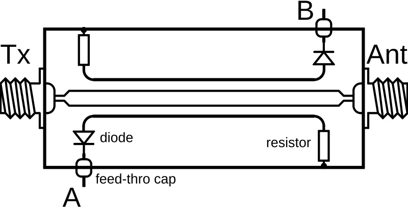
A meter connected between point A and earth will indicate
2025-Full3576
An air cored inductor has a positive temperature coefficient of inductance. Capacitors can be obtained with either positive or negative temperature coefficients. The combined temperature coefficient of the capacitors in a tuned circuit should be
2025-Full3590
The sensitivity of a receiver is being checked. The RF signal generator will only go down to 20µV so an attenuator giving 2µV is fitted. That is an attenuation of
2025-Full3614
A 1 to 30MHz HF transmitter is checked against a very accurate off-air frequency standard to within 100Hz. The specification of the transmitter crystal oscillator is 0.1ppm per degree C and an ageing drift of 5ppm per year. The room and crystal temperature vary by up to 10 degrees. The earliest that the transmitter may be outside its 500Hz accuracy specification will be during
2025-Full3647
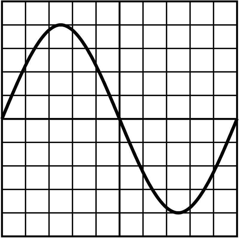
The oscilloscope displaying the waveform shown is set to a sensitivity of 5mV per division and timebase 1ms per division. What is the peak amplitude of the waveform?
2025-Full3655
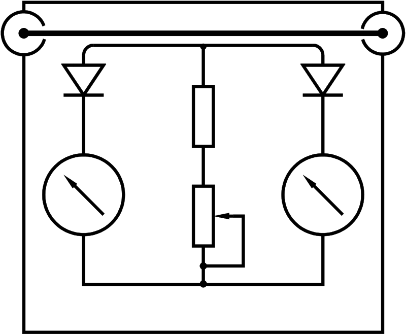
What device is shown in the circuit diagram?
2025-Full3656
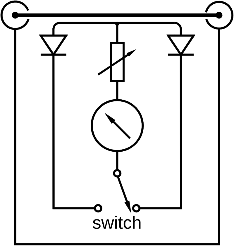
In the device shown the switch would be labelled
2025-Full3812
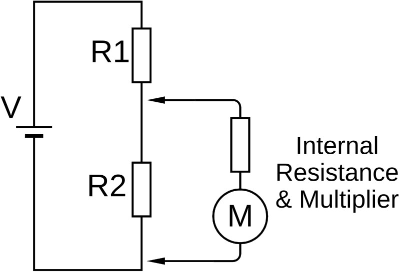
In the circuit below the battery supplies 12 Volts and R1 and R2 are both 100kOhms. Which combined internal resistance and multiplier resistor in the voltmeter will have the LEAST effect on the circuit being tested?
2025-Full3814
When making voltage measurements with an analogue volt-meter, you suspect that the meter may be affecting the operation of the circuit. A simple way of checking this is to:
2025-Full3815
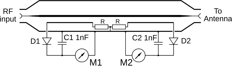
In the diagram below, the two meters are used to indicate
2025-Full3830
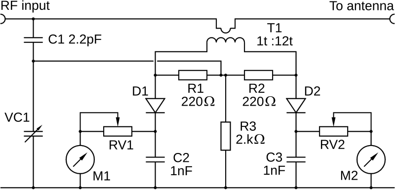
In the diagram below, what are the two meters used to measure?
2025-Full3831
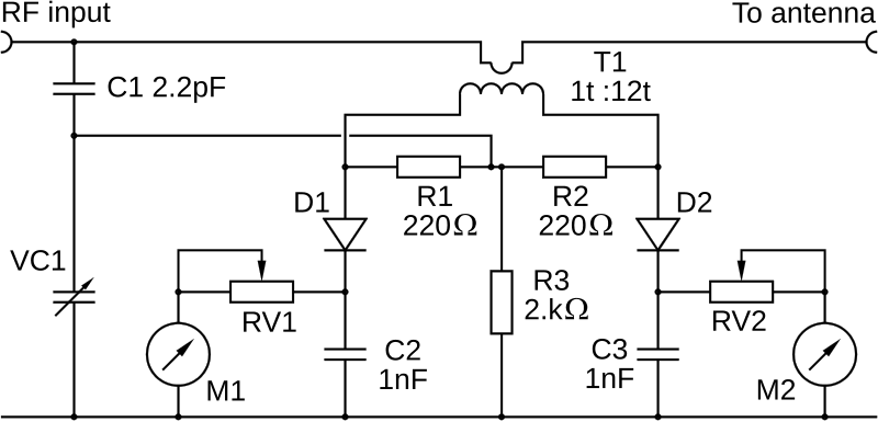
The circuit below shows
2025-Full3925
What will be the maximum frequency error of the 7th harmonic of a 10MHz crystal calibrator when it has been adjusted using a frequency counter which has a clock accuracy of 3ppm?
2025-Full3926
A 10MHz quartz crystal oscillator is understood to have a negative frequency drift of 2ppm/year. What would you expect its frequency to be, 3 years after calibration?
2025-Full3927
You wish to transmit a 3kHz wide, USB signal on the 17m band (18.068 MHz to 18.168 MHz) using a transmitter that is fitted with a free running Variable Frequency Oscillator (VFO). The VFO frequency is known to drift upwards at 850Hz/hr. What is the highest dial frequency you could use for 2hr whilst being sure you are still operating within band?
2025-Full4005
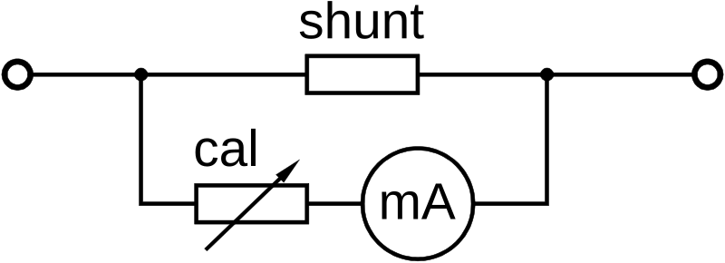
The drawing shows an ammeter circuit used to monitor the current in a power supply. The variable resistor has a maximum value of about 10% of the resistance of the meter movement and is used for calibration. Modifications have increased the supply from a maximum of 2A to 5A and the meter circuit needs to be modified accordingly. What change is needed to accomplish this?
2025-Full4006
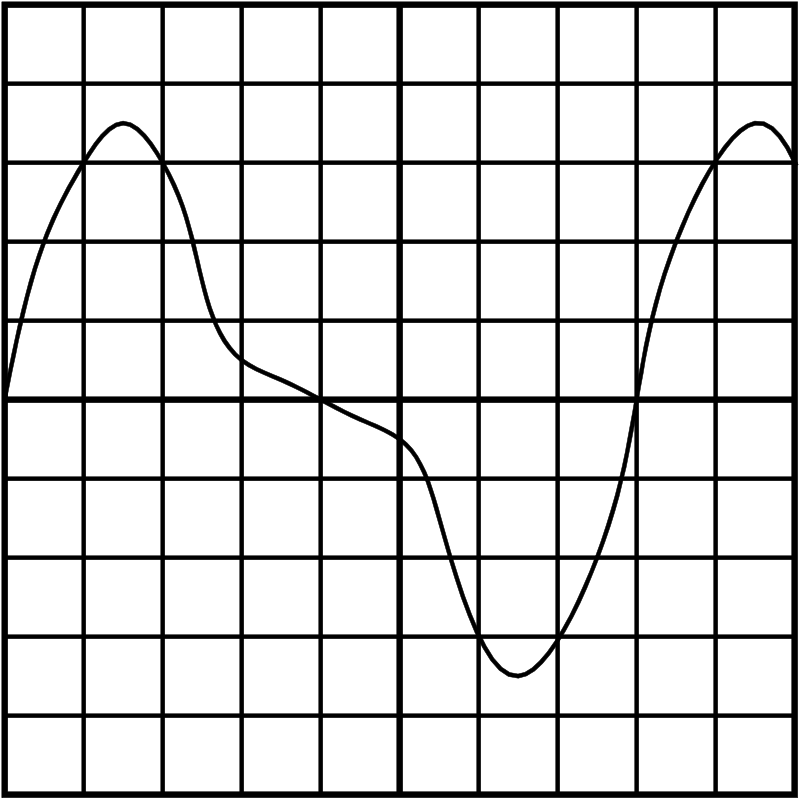
The diagram shows an oscilloscope trace of a sine wave with significant second harmonic distortion. The oscilloscope settings are; time base 500ns/division, y-axis 20mV/division. What is the frequency of the fundamental signal and its peak amplitude?
2025-Full4007
The trace on an oscilloscope occupies most of the height of the screen and about two cycles are shown across the screen but is drifting to the left. To stabilise the drift which control should be adjusted?
2025-Full4025
An oscilloscope is displaying 10 cycles of RF from a transmitter on the 20m band. The transmitter is changed to the 40m band. Which adjustment should be made to display 10 cycles on the new band?
2025-Full4038
A frequency counter has a 10MHz oscillator known to be accurate to 100 parts per million and this has been used to measure the carrier frequency of an FM transmission. The transmission bandwidth is 10kHz. What is the highest dial frequency that the operator may set on the 28MHz band to be confident that their signals remain within the allowed amateur band?
2025-Full4039
A frequency counter is used to measure the frequency of a very accurate 10MHz oscillator and the readout says 9.999000MHz. This counter is then used to measure the frequency of a 2m transmitter and it reads 144.300000MHz. What is the frequency of the transmitter?
2025-Full6055
A crystal oscillating at 8100kHz has a temperature coefficient of -23ppm per degreeC. It was accurately calibrated at 20°C. What is the frequency of oscillation at 65°C?
2025-Full6058
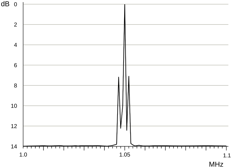
Which control should be adjusted to show the sidebands of an amplitude modulated signal more clearly?
2025-Full6060

What is the level of the second harmonic of the 1.8MHz transmission?
2025-Full6061

What is the level of the third harmonic of the 1.8MHz transmission?
2025-Full6063
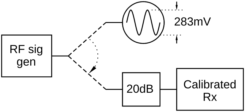
An RF signal generator has a 50Ω output impedance and is able to produce signals up to 1V rms. The output is adjusted using a high impedance oscilloscope to display a trace of 283mV peak to peak. The oscilloscope is disconnected and the sig gen is then connected to a 20dB attenuator to a receiver which displays the rms signal voltage at its input. What reading is expected?
2025-Full7644
A home made transmitter uses a crystal at 3.5MHz multiplied up to 28MHz. The crystal is specified as 0.5ppm per degree C. At switch on the room is at 18C but inside the transmitter case is 36C when warmed up. By how much will the transmitted frequency vary in that time?
2025-Full7964
An RF amplifier is required to bring the 200mV output from an oscillator up to 4V to drive the output transistors in a transmitter. How much gain will you need?
2025-Full7965
An RF preamplifier is required to bring the 0.2µV signal from the antenna to the 8µV required by the main receiver for best noise performance. What is the preamplifier gain?
2025-Full7997
An oscilloscope is being used with a half-wave dipole antenna to monitor a received signal. The trace shows 282mV peak-to-peak. However when you also connect this assembly to your radio receiver it shows 6dB lower. Why?
2025-Full830
An oscilloscope is displaying an AC signal showing 6 cycles across 6 divisions on the x-axis of the screen. The time base is set to 10ms per division. What is the frequency of the AC signal?
2025-Full833
An oscilloscope is displaying an AC signal showing 5 cycles across 5 divisions on the x-axis of the screen. The time base is set to 5µs per division. What is the frequency of the AC signal?