
Full Level: Feeders and antennas
Full Level: Feeders and antennas
Part of the official RSGB Full Level question bank, filtered to the Feeders and antennas syllabus section.
- 50 questions in this section
- Some questions include a reference diagram or circuit image
Before you start, you may want to open the official RSGB reference data sheet (band plans, frequency tables, conversions) — it's allowed for use during the real exam too.
2025-Full3659
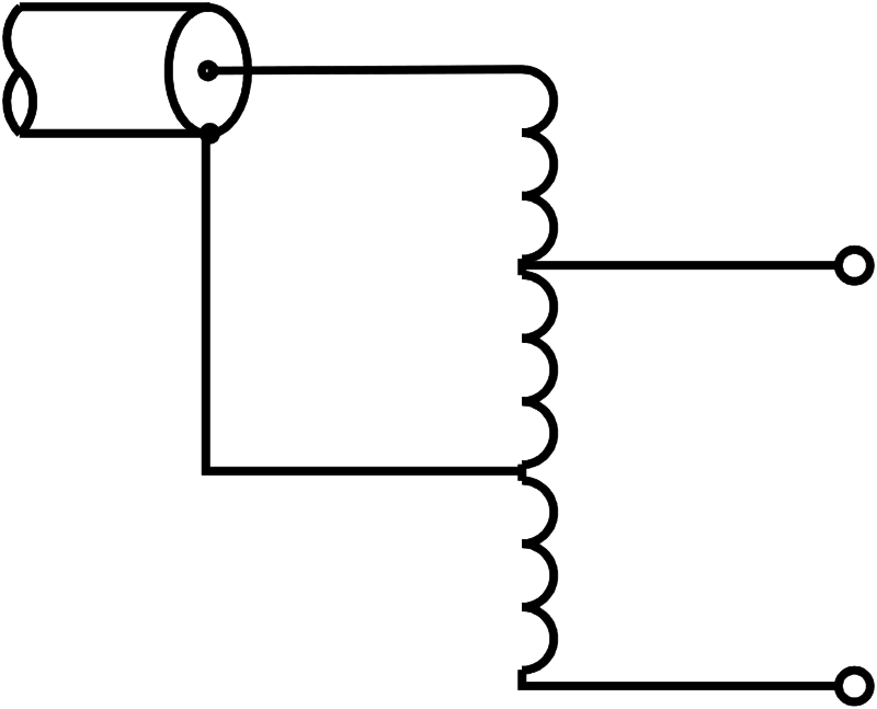
The circuit is a
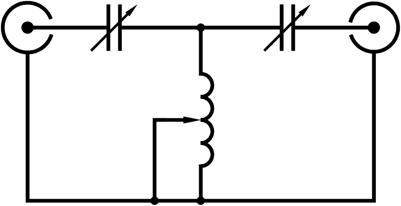
2025-Full3675
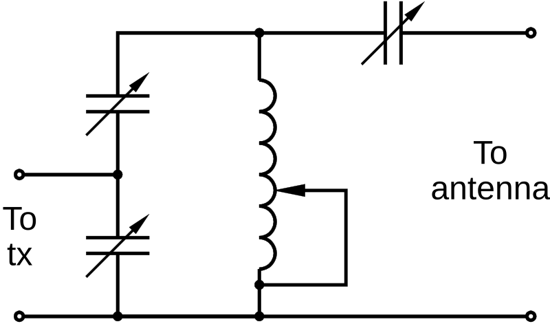
The diagram shows the circuit of an antenna tuning unit (ATU/AMU). When correctly adjusted it is intended to
2025-Full3737
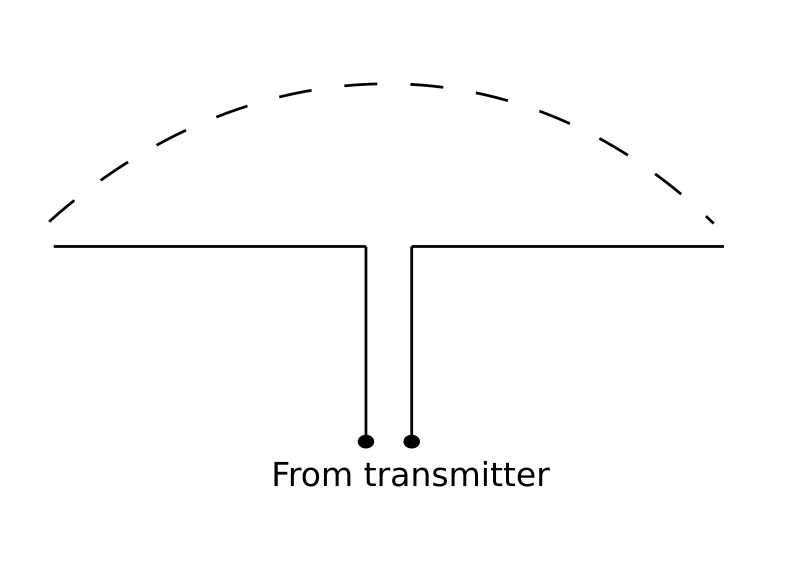
The figure shows a half wave dipole fed from a transmitter. The dashed line represents the antenna's
2025-Full3738
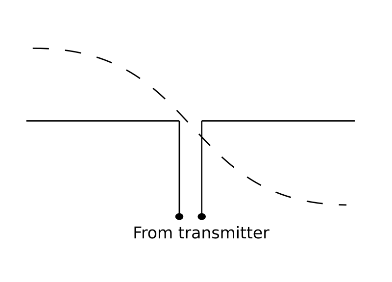
The figure shows a half wave dipole fed from a transmitter. The dashed line represents the antenna's
2025-Full3739
A folded dipole has been used in a VHF directional antenna in order to
2025-Full3750
If an Antenna Matching Unit (AMU/ATU) is installed between the transmitter and the feeder to the antenna, and correctly adjusted it will
2025-Full3817
When used as intended, an antenna matching unit (AMU/ATU) is designed to reduce
2025-Full560
Due to the Velocity Factor, the physical length of antenna feeder is
2025-Full561
A length of coaxial cable with a polythene dielectric is cut to λ/4 at 10MHz. The physical length will be approximately
2025-Full562
The ratio of the wavelength of a signal in a coaxial cable to the wavelength in free space is a measure of the
2025-Full563
A λ/4 length of solid polythene coaxial cable is required to match an antenna for the 2 metre band. Its length will be approximately
2025-Full565
An antenna has a feedpoint impedance of 100Ω at the frequency in use and is fed via 75Ω coaxial cable cut to λ/4 at the frequency in use. What impedance will the transmitter see?
2025-Full566
An antenna has a feed impedance of 100Ω. A λ/4 feeder to transform this to 50Ω will have an impedance of approximately
2025-Full570
Which of the following is NOT a type of balun?
2025-Full571
What would the advantage be fitting a 1 to 1 (1:1) balun to the centre of a dipole antenna of an amateur transceiver fed by coaxial cable?
2025-Full573
A coaxial feeder cable is being used to feed a centre-fed half wave dipole. To reduce RF currents on the outer braid of the feeder; a length of braid from a larger cable is fitted over the outer insulation of the feeder. This braid should be
2025-Full574
Because of the end factor correction, the actual length of a λ/2 dipole antenna is approximately
2025-Full575
For a 30MHz half-wave dipole antenna, the length of wire on each side of the central insulator is approximately
2025-Full582
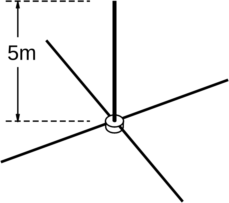
If the antenna shown was fed with a signal in the 14MHz band the feed-point impedance would be approximately
2025-Full583
The feed point impedance of a half-wave dipole antenna is between
2025-Full587
Placing passive conducting elements close to a dipole will affect the radiation pattern of the dipole to make it directional. It will also
2025-Full592
The sum of the forward and reverse signal voltages on a feeder, divided by their difference, is known as the
2025-Full594
If the forward signal on a feeder is 100V and the reflected signal is 10V the standing wave ratio is
2025-Full597
A suitable meter in a coaxial cable indicates that the voltage of the RF signal from the transmitter is 12V and the reflected signal voltage from the antenna is 2V. The SWR at that point is
2025-Full599
You are asked to choose between two antennas on the basis of the results of return loss measurements on each of them. Antenna 1 has a measured return loss of 10dB and antenna 2 has a measured return loss of 20dB. Which antenna should you choose?
2025-Full600
A transceiver is connected to a length of feeder of loss 3dB but the far end is left disconnected. A forward/reverse power meter reads 8W forward power. What will the reverse power reading be?
2025-Full601
A suitable meter in a coaxial cable indicates that the voltage of the RF signal from the transmitter is 10V and the reflected signal voltage from the antenna is 1V. The Return Loss is
2025-Full602
A transmitter feeds an antenna using a short length of good quality coaxial cable but the matching between the cable and the antenna is very poor. The transmitter will 'see'
2025-Full603
A transmitter is feeding a length of coaxial cable connected to an antenna, which is poorly matched. Rain seeping into the cable increases its attenuation by some 6dB. The effect at the transmitter will be that the SWR
2025-Full604
The return loss of an antenna is noted as being 16dB. When installed the feeder is 10 metres long. If the feeder has a loss of 0.2dB/metre, the expected return loss, measured at the transmitter, will now be
2025-Full607
If RF losses in a feeder are high the SWR measured at the transmitter will be
2025-Full608
The return loss of a feeder and antenna is measured as 30dB. If the feeder has a loss of 3dB, the return loss of the antenna is
2025-Full609
The return loss of an antenna is measured as 20dB. The antenna is installed using 10m of feeder, which has a loss of 0.5dB per metre. The return loss measured at the transmitter will be
2025-Full610
A transmitter is connected to a length of feeder of loss 3dB and an antenna with a return loss of 15dB. What return loss will be seen at the transmitter
2025-Full718
A λ/4 coaxial line transformer using air spaced coaxial cable is replaced with one using a solid polythene dielectric. The length of the replacement cable will be
2025-Full719
It is desired to match an antenna of 100Ω impedance to a transmitter of 50Ω output using a short length of 72Ω feeder as an impedance transformer. Its length should be
2025-Full720
A 100Ω antenna is feeding a receiver with a 50Ω input impedance. It is decided to improve the matching by inserting a λ/4 length of coaxial cable as an impedance transformer. The characteristic impedance of this cable should be
2025-Full746
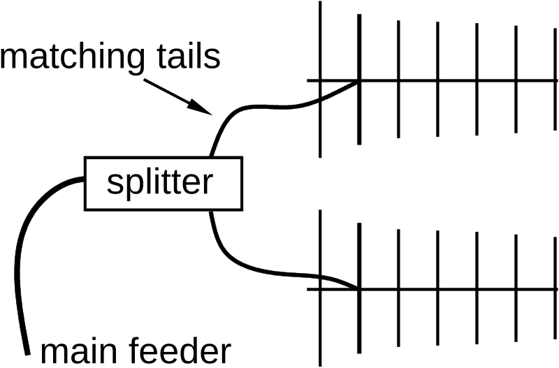
Two 50Ω Yagi antennas are connected by a λ/4 splitter to match 50Ω feeder. The characteristic impedance of the two λ/4 sections should be about
2025-Full7908
A VHF FM broadcast programme on 100MHz is suffering interference from a 2m transmission nearby. A stub filter is proposed, a length of solid polythene dielectric coaxial cable to be connected in parallel with the existing feeder from the aerial in the roof. The coax stub should be about
2025-Full7911

The drawing shows a sleeve balun. How long should the sleeve be, and at which end should the sleeve be connected to the outer braid of the coaxial feeder?
2025-Full7914
How long is a typical half wave dipole tuned for the centre of the 1.8MHz band?
2025-Full7916
How long is the optimum length of a half-wave dipole for the centre of the 3.5MHz - 3.8MHz band?
2025-Full7917
A directional power meter shows 400W from the transmitter and 25W reflected from the antenna. An SWR meter is then substituted for the power meter. What approximate reading is expected?
2025-Full7918
A Radio Amateur wants help with their antenna matching. If the forward power to an antenna and feeder is 9W and the reflected power is 1W then the SWR is approximately
2025-Full7919
A directional power meter shows 400W from the transmitter and 25W reflected from the antenna. The Return Loss is
2025-Full7920
A Radio Amateur wants help with their antenna matching. The power meter shows 9W from the transmitter and 1W reflected. What is the Return Loss?
2025-Full7922
Four Yagis are connected together to give increased gain. Each has a feed impedance of 50Ω and have λ/4 tails of 75Ω coax to a common point where they are all paralleled together. Another λ/4 length is used to match to the 50Ω main feeder. What characteristic impedance is ideally needed?
2025-Full825
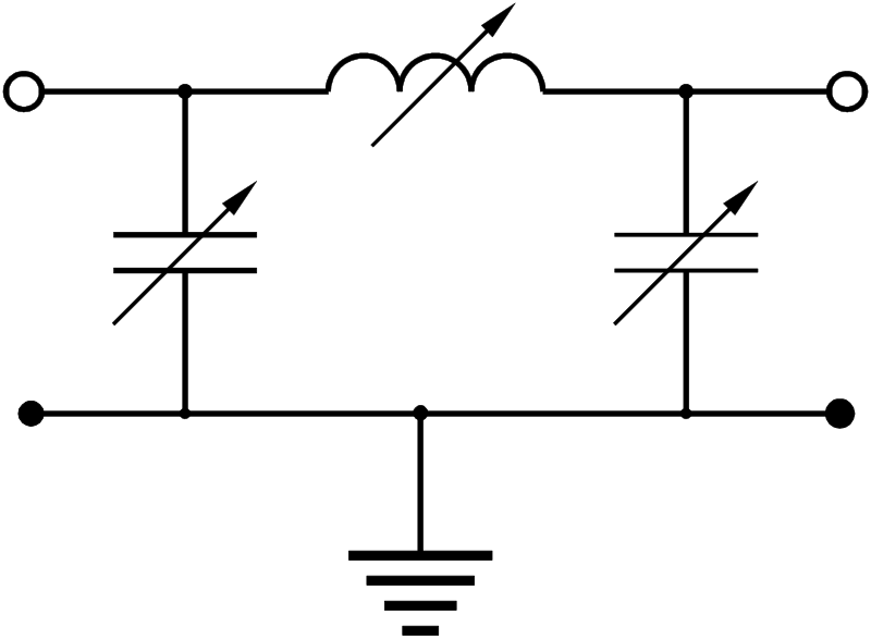
The diagram shows
2025-Full829
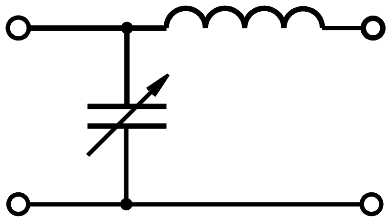
The diagram below shows
2025-Full849
The diagram shows